Post by @gloriouscow@oldbytes.space

so there's a rumor you can tickle the NEC uPD765 floppy controller just right and it will whisper sweet nothings in your ear
those sweet nothings being its microcode.
now, we already have the 765's microcode ROM array dumped via die photography thanks to @infosecdj .
so why might we want to proceed with the tickle party?
because the microcode ROM doesn't make any damn sense, that's why. so i'm curious if the debug mode might dump out something in a different order.
plus i'm just curious to see if I can figure out the method in the first place.
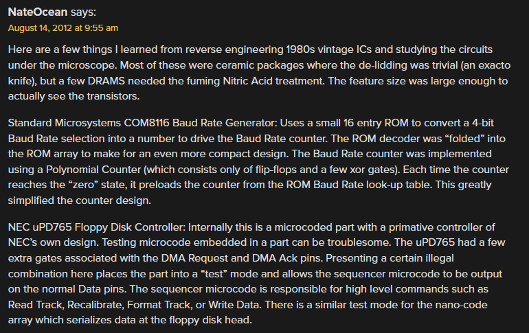
this rumor comes from a 14-year old comment Hackaday from a user 'NateOcean'.
Unfortunately nobody knows who the hell NateOcean is and he did not elaborate.
But thanks to him we know we have to tickle the DMA lines.
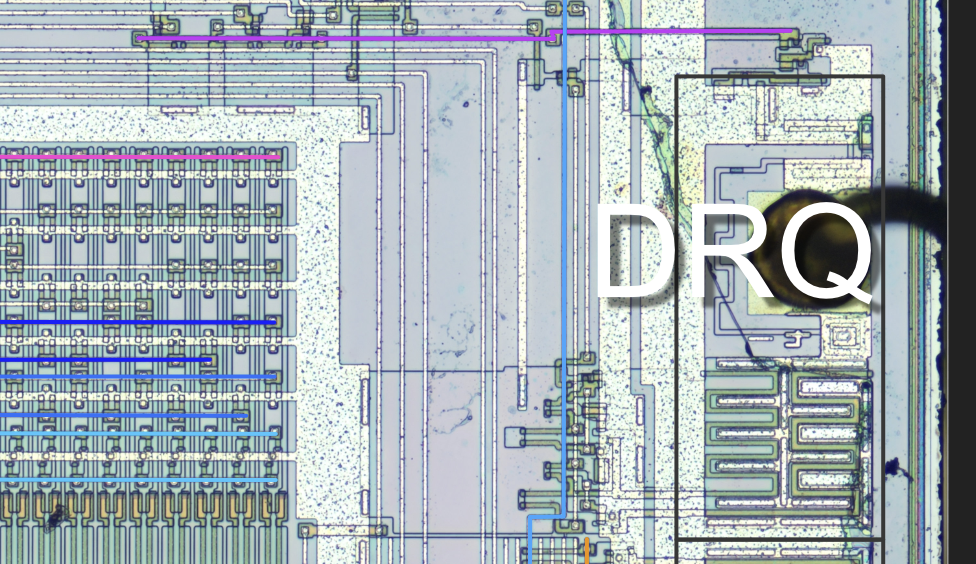
Our friend Nate leaves us with many ambiguities. What's an "illegal combination" of the DMA lines?
Well, DRQ is an output pin.
So it would be rather odd to see that it sure looks like its bidirectional.
8 likes
 MrTrololo@MrTrololo@social.subpolygon.com
 DJ🌞:donor:@infosecdj@infosec.exchange
 Ray McCarthy@raymaccarthy@mastodon.ie
 twi@confusomu@twoot.site
 alina🐾💖✨🏳️⚧️@alina@girldick.gay
 PurpleJillyscreams :YuriScream:@PurpleJillybeans@kind.social
 Rue Mohr@RueNahcMohr@infosec.exchange


 💾@JennyFluff@chitter.xyz
I mean if I was a fancy-pants NEC chip designer and I wanted to give my chip a microcode-yodelling debug mode using pin tickling i'd logically make it check said tickled pins during reset.
i could be wrong here! but it's good as any guess at the moment.
but then how does the microcode get read out? does it just come tumbling out as we clock the chip? do we have to toggle some other pin to advance it? who knows!
i figure we assert /CS and /RD and keep clocking it and if nothing exciting happens we can try twiddling /RD on and off.
I'm going to use my new best friend, the Pi Pico 2.
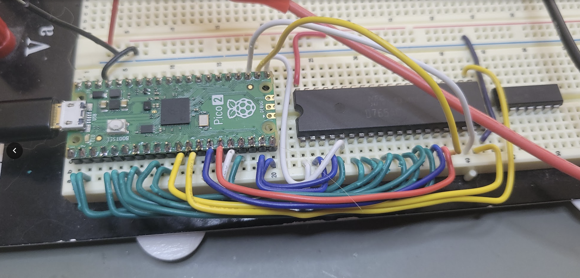
here's the probe rig wired up. complete with cat hair

i added a bypass cap for the 765 and tied some of the unused inputs to ground, but i don't feel like taking another picture
initial check looks good - we're able to reset the 765.
I'm actually able to read 0x90 from the main status register which is remarkably plausible.
That's RQM and BUSY.
The 765 actually takes some time to reset itself, a delay I found it necessary to emulate in MartyPC.
Eventually it will assert an interrupt, indicating it has done its hair and nails and is ready to go out.
If DRQ really is a magic debug tickle input, it's probably only an input during RESET.
We can try to determine that - we can use the Pico's internal GPIO pullup to try to test whether DRQ is being driven low.
if we can pull it high, then that's a hint that that it might be in input mode
Sure looks like it's being driven. Some other condition might unlock its input-ness.
There's a very real chance I never actually figure this out, at least not without analyzing the die more.




@gloriouscow If the die photo gave you the ROM in physical layout order and the tickle dump walks it in execution order, the diff between the two is the sequencer's address map, which might be the more valuable artifact. You'd learn the microcode ordering without decoding a single microinstruction. And if the tickle dump comes out identical to the die photo, that says the debug port is just a ROM reader with a linear counter, which at least settles what the mode is for.
@gloriouscow Nothing yet is consistent with the mode being reset-latched rather than a runtime command. NateOcean's 'illegal combination' reads more like a key the chip samples during reset than something a running 765 would answer to. Worth one pass with the DMA lines driven into the illegal state and held static across a reset edge before clocking. If the bus does something odd on the first /RD after that, the rumor holds. If it stays silent even then, the tickle probably needs a sequence, not a state, and that's a much bigger search space.